

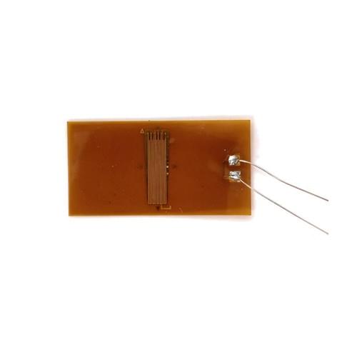
Universal Foil Strain Gauges
$100.00
Three carrier materials map onto three typical duties. The BE series uses a phenolic–acetal carrier with Constantan foil in a fully sealed construction — flexible, easy to bond and stable, aimed at 0.05-class precision sensors and general stress analysis. The BA series uses a polyimide carrier with Constantan foil, also fully sealed: high elongation, good moisture and heat resistance and excellent dielectric properties, offered in a room-temperature type (≤ 80 °C) and a medium-temperature type (≤ 150 °C) that must be stated when ordering, for example BA350-3HA150(11). The BQ series uses a paper-impregnated phenolic carrier with Constantan foil — thin, soft and easy to bond, the common sensing element for concrete and similar non-homogeneous materials, available at 120 Ω only.
Table 1 Technical data: universal and specialist series
Series Resistance (Ω) Tolerance Gauge factor Strain limit Fatigue life Service temp. (°C) Typical use
BE 60 / 120 / 350 / 650 ≤ ±0.1 % 2.00–2.20 2.0 % 10⁷ –30 to +80 Precision sensors (0.05 class), general stress analysis
BA 120 / 350 ≤ ±0.1 % 1.86–2.20 2.0 % 10⁷ –80 to +150 Medium-temperature analysis, humid and hot conditions
BQ 120 ≤ ±0.1 % 2.00–2.20 2.0 % 10⁷ –30 to +80 Concrete and other non-homogeneous materials, single-use tests
BB / BAB 250 °C 120 / 350 ≤ ±0.15 % 1.86–1.98 1.5 % 10⁷ –269 to +250 High-temperature components and sensors
TJ underwater 120 / 350 ≤ ±0.15 % 2.00–2.20 2.0 % 10⁸ –30 to +60 5 MPa hydrostatic pressure, cabin sealing tests
TA large strain 120 / 350 ≤ ±3 % 2.00–2.20 5 %–20 % — –30 to +150 Elastic–plastic stress–strain analysis
BE residual stress 120 ≤ ±0.15 % 2.00–2.20 2.0 % 10⁷ –30 to +60 Hole-drilling residual-stress measurement
Table 2 BE120-3AA(11) technical specifications
Parameter Specification
Model / series BE120-3AA(11) · BE universal series, foil type
Grid structure AA — single-axis horizontal grid, for tension, compression and bending strain
Nominal resistance 120 Ω (60, 350 and 650 Ω available in the same series)
Resistance tolerance ≤ ±0.1 % on the mean
Gauge factor 2.00–2.20
Gauge-factor scatter ≤ ±1 %
Strain limit 2.0 % (≈ 20 000 µε)
Fatigue life 10⁷ cycles
Temperature self-compensation Code 11 — alloy steel, martensitic stainless steel, precipitation-hardening stainless steel
Compensated expansion coefficient α ≈ 11.3 × 10⁻⁶ /°C; no thermal-output correction required inside the compensated range
Service temperature –30 to +80 °C
Grid size (L × W) 2.8 × 2.0 mm
Carrier size (L × W) 6.4 × 3.5 mm
Carrier material Phenolic–acetal base, fully sealed construction
Grid foil Constantan foil
Termination options C open solder tabs · D self-contained solder pads · F no leads · U leads, open type · X sealed, soldered leads · P/X/BX/Q/G sealed leads (PVC, round, flat-ribbon, lacquer-coated, high-temperature)
Lead length Specified in millimetres as the suffix (※※)
Recommended adhesive H-610 or H-600 high-performance epoxy for precision work; B-702 cyanoacrylate for room-temperature static tests
Protection AZ-709 waterproof coating; G-704 / G-D04 RTV silicone for exposed locations
Soldering temperature ≤ 250 °C, short dwell time
Standards OIML 62 · GB/T 13992-92 “Resistance Strain Gauge”
Compliance RoHS
Customisation Any grid shape and size produced in batches from drawing or sample
Packing / MOQ / lead time [to be confirmed]
Table 3 Termination suffixes
Code Termination Lead
C Open solder terminals None
D Self-contained solder pads None
F No lead wires, open type None
U Lead wires, open type Standard
X Standard lead-wire soldering, sealed type Standard
P※※ PVC lead wire, sealed type Length in mm
X※※ Round lead wire, sealed type Length in mm
BX※※ Flat-ribbon lead wire, sealed type Length in mm
Q※※ Lacquer-coated lead wire, sealed type Length in mm
G※※ High-temperature lead wire, sealed type Length in mm